Project LANA interim report on IUT theory,
“As of July 2026, the LANA Project has not made a final judgment on
the correctness or incorrectness of IUT theory. However, through the
multiple bootcamps held since February 2025 and lively discussions
during numerous online meetings, it has progressed to the point of
transforming the core of the controversy, which for many years had
been discussed in vague terms, into the form of diagrams, types, code,
black boxes, and explicit questions”, and later: “we are reserving our final
judgment on whether a proof exists for Corollary 3.12 in Mochizuki’s
third paper on IUT theory.”
Silk, a cooperative fiber scheduler for Linux with per-CPU scheduler
threads, io_uring integration, and topology-aware work-stealing.
By ClickHouse.
Project LANA is real interesting. The math is all far far above my head, but I think it represents something important: a collaborative effort among mathematicians to use formal computer-verified proofs to resolve disagreements among people who have carefully studied a proposed proof and find themselves in disagreement.
I don't know which way this particular question will be resolved (currently, LANA is finding that the Corollary 3.12 question raised by Scholze and Stix is proving hard to formalize but has not found a formalization that confirms or contradicts Mochizuki) -- but the meta-result of *whether* the formal methods will ultimately serve to drive a consensus in this case is what will be interesting to see. Personally, I hope LANA is successful at formalizing AND that their final formalization does become the point of consensus about IUT.
The other main possible outcomes: * An "unaided" human outside LANA finds a persuasive argument not yet in the public record, which is then used by LANA to finish formalization. This would be great. For now, as I understand it, LANA is not sharing their repository of Lean code, so others can't yet directly contribute to the formalization. * An "unaided" human outside LANA finds a persuasive argument that creates consensus. In this case LANA might find it is not sufficiently interesting to finish their formalization. This would be too bad, and not settle the meta-question. * LANA never conclusively formalizes the model to the point where it offers a resolution to the Corollary 3.12 question. Unfortunate, and would point to limits at our ability to formalize with systems like Lean. * LANA produces what they believe is a formal result, but still fail to achieve consensus in the community. Unfortunate, and would point to limits in formal methods at being persuasive to practicing mathematicians.
One of the features of systemd that is most controversial is the option to kill user processes when the user logs out. That initially killed screen/tmux/nohup processes too. In recent Debian releases the default configuration of systemd-logind (the login manager for systemd) is to allow processes to keep running, the configuration file /etc/systemd/logind.conf has an option KillUserProcesses that can be enabled to have user processes killed. If you do that then there are options to only kill processes for certain users and to exclude some users (default to excluding root). If using that option you can apparently use a systemd unit to start screen which prevents it being killed on logout.
This is a very handy feature for some particular user cases. One situation was that I was supporting some people who weren’t very good at computers on a system running KDE and some KDE processes would linger. So the option of logout and login again to deal with an issue of akonadi or some other KDE service misbehaving didn’t work. On that system I enabled the option to kill user processes which reduced the number of problems they had while not requiring rebooting.
It is widely believed that the “linger” feature is required to allow screen/tmux/nohup to work, in Debian (and probably most distributions) that is not the case. It might be that some combinations of configuration requires “linger” to allow screen/tmux to work but I am not interested in trying to discover them. Of all the people I have directly supported for Linux desktop use (which numbers in the hundreds) none of them have had the ability to use screen/tmux and also the cluelessnes that makes me want to automatically kill their processes when the logout.
Controlling Linger
You can enable and disable “linger” for your own account with the following commands if polkit is installed and in a typical configuration:
loginctl enable-linger
loginctl disable-linger
If running as root you can enable and disable it for another user with the following commands:
There doesn’t seem to be any documented way of discovering if an account has linger enabled or for listing accounts that have it, it seems that “ls /var/lib/systemd/linger” is the only option.
Linger on Debian
On a Debian system with close to default settings the processes won’t be killed on logout and the only difference “linger” makes is to start programs in the user’s context BEFORE they login. A friend was recently testing out a bunch of LLM programs on one of my servers and the account he used for that ended up with “linger” enabled, presumably one of the install scripts he ran was written on the assumption that enabling linger was necessary for nohup to work and it did so automatically without being asked.
One benefit I’ve found from this behaviour is on my laptop. I’m currently testing out new SE Linux policy on my laptop and rebooting it a lot. When I enabled linger on my account it caused the laptop to connect to wifi on boot without needing to login which is convenient. I can then ssh to it even when the X11/Wayland login configuration is broken.
I will leave it enabled after finishing these tests. Having background processes like Pipewire and Bluetooth start before I login will presumably make things slightly faster when I do login.
Related posts:
Systemd Notes A few months ago I gave a lecture about systemd...
We launched GitHub Sponsors in 2019 with a simple belief: the people who build and maintain open source software deserve to be supported for their work. Since then, tens of thousands of sponsors—individuals and organizations alike—have turned that belief into action.
We’re proud to announce that more than $100 million has been invested in open source maintainers and projects through GitHub Sponsors. This milestone belongs to the developers, organizations, and maintainers who have invested in a more sustainable open source ecosystem, and it signals that the way we value open source is changing.
How we got here
GitHub Sponsors started with individuals. We wanted to make it possible for any developer to directly support the maintainers they depend on. In 2023, we made organization-funded sponsorships generally available and saw organizations like Shopify step up to fund their dependencies at scale. The program expanded to 103 regions, partnered with Patreon, and introduced tools like bulk sponsorships and invoice payments to make it easy to participate.
The result: a global funding network that supports over 70,000 maintainers and organizations, and includes more than 280,000 sponsors spanning individual developers to Fortune 500 companies.
The pace is accelerating, too. The first $10 million took nearly two years. The most recent $10 million took just five months.
The people behind the number
While $100 million is a meaningful number, the real measure of impact is what it’s made possible for real people.
GitHub Sponsors changed how I think about open source. It gave me a direct, sustainable way to fund the time it takes to build and maintain projects, instead of treating it like side work. That has let me invest more consistently in the projects and build with a much longer-term view. Thanks to GitHub Sponsors, I am able to give back to our community, build a business, and actually make a difference in OSS.
Kelvin Tegelaar, Maintainer, Lime Networks
Shopify invests in open source because our platform, our merchants, and our engineering culture all depend on a healthy open source ecosystem. GitHub Sponsors gives us a direct way to support the maintainers and projects that move the industry forward, from foundational technologies to smaller tools that make developers’ daily work better. For us, sponsorship is both practical and values-driven: it helps sustain the software we rely on while strengthening our connection to the people building it.
Shopify
As strong advocates of open source software, Mercedes-Benz recognizes the incredible contributions made by developers and maintainers worldwide. Through GitHub Sponsors, we aim to support and empower these dedicated individuals and projects that drive innovation, collaboration, and the advancement of open source. By providing financial assistance to these projects, we hope to enable them to dedicate more time and resources to their impactful work, thereby making open source more sustainable and contributing to the overall health and longevity of the projects. We extend our deep gratitude to all the participants and celebrate their dedication. Together, we can continue to foster a vibrant and sustainable open source ecosystem that benefits our teams, developers and users alike.
Dr. Wolfgang Gehring, OSPO Lead & FOSS Ambassador, Mercedes-Benz Tech Innovation GmbH
GitHub Sponsors has meant many things for me and my open source. First, it showed me people’s appreciation and motivated me. Then it showed me I could and should figure out how to do more open source. And then, for the past years, it has also allowed me to sub-sponsor many of the open source tools that power mine, to share that appreciation and support.
Sebastián Ramírez, tiangolo
My projects wouldn’t be what they are today without GitHub Sponsors. Sponsorships allowed me to quit my job and work on them full time. GitHub Sponsors opened my eyes to the opportunities available for passionate people working on projects that people care about.
Caleb Porzio, Livewire & Alpine.js
Open source careers shouldn’t depend on geography or circumstance. They should depend on the value of the work. Increasingly, the community is making that possible.
What we’ve learned
Building GitHub Sponsors over the past seven years has taught us a few things:
Organizations move the needle. In 2022, nearly 40% of sponsorship funding came from organizations, with each organization-funded sponsorship worth an average of nearly 15x more than the average individual sponsorship. As more companies recognize their dependence on open source, this share continues to grow.
Reducing friction matters. Every time we’ve made it easier to sponsor (e.g. adding invoice payments, expanding regions, enabling bulk sponsorships) we’ve seen a corresponding increase in funding. The demand to support open source is there. We aim to make that easy to do.
What’s next
This milestone proves that when the community shows up for open source, the impact is real. But the work isn’t done. The open source funding gap is still enormous, many critical projects remain underfunded, and maintainer burnout continues to be one of the biggest risks to the software supply chain. This $100 million is proof that the community can change how open source is sustained, one sponsorship at a time.
The best way to keep this momentum going? Start sponsoring the projects you depend on or encourage your organization to do the same.
How you can get involved
Behind the scenes, maintainers are working daily to make open source better for all of us. If you or your organization depend on open source — and you almost certainly do — there’s no better time to invest in the people who make it possible.
Visit the Sponsors Explore page to discover which maintainers you depend on and start supporting them today. If you’re a maintainer and haven’t set up your Sponsors profile yet, visit github.com/sponsors to get started.
Thank you to every sponsor and every maintainer who has been part of this $100 million journey. This is what happens when a community decides that open source is worth investing in. We can’t wait to see where it goes from here.
With Nintendo’s 3DS experiencing a bit of a renaissance lately, prices for functioning systems have shot through the roof. Getting a busted one with a broken screen is a lot cheaper, but then you run into the eye-watering price difference between a replacement top screen for the regular version and the larger XL variant. The latter costs about the same as a whole new used 3DS, while the former goes for peanuts. Here the solution is obvious, with [Skawo] demonstrating how they hacked the cheaper, smaller top screen into a New 3DS XL.
The price difference on AliExpress as shown in the video is on the order of $120, with the smaller screen going for less than $10. Since they both use the same connector pin-out and display technology, you can plug either display into the New 3DS XL mainboard.
Where you’ll run into issues, other than the replacement display being obviously not XL, is the physically shorter flat flex cable for the controls that forces the display to be installed in an offset manner. You need jailbroken firmware like Luma3DS here to adjust for the screen offset. Filling in the missing screen real-estate is the other issue you have to patch over somehow, which was done here in barbaric fashion with some cardboard.
Beyond that it does work, and as a fix to at least get a broken New 3DS XL back into the game it’s worth considering. Do note that there’s a difference between regular 3DS and New 3DS (second generation) screens with neither being compatible, so be careful before you try such a fix.
I've been trying to make some time for Open Source projects again. I've been using LLMs for much of the coding because the vast bulk of it at this point is just grunt work. First up is PyOpenGL. The tests the LLM produced turned up a bunch of bugs in the core that have lain dormant for years because the endpoints weren't getting used. The LLM tests are not particularly fun or interesting, but they did a pretty good job of finding wrapping errors. They also exercised GLES and EGL enough to make it far more reasonable to actually use those two interfaces.
Shout out to glfw python library for working cleanly on the Wayland only environment. Definitely helped to find the hidden GLX dependencies we had throughout the Linux platform implementation. One of the biggest ones there was the GLUT library. The other thing that came out was the GLE library being legacy (compatibility) OpenGL.
PyOpenGL 4.0.0a1 is classified as a major release mostly because of the abandonment of old Pythons (<3.9) and old Numpy (<2). Other than that there's mostly just bug-fixes that came from the new test suites.
GLU * gluUnProject4 missing arguments * gluNewQuadric/gluQuadricCallback fix the callback mechanism to work like Nurbs code * gluTessVertex/gluTessBeginPolygon and combine callback, original object return fixes * gluGetNurbsProperty added, allocates the output * gluNurbsCallbackData(EXT) argtype fix
glGet Sizes * sizing tables regenerated based on results from size probing, lots of incorrect sizes fixed; note that these fixes are constrained to extensions I happen to have access to on my platforms * fix the code generator's constant generation * glGetPolygonStipple fixed size output * glGetCompressedTexImage glGetTexImageCompressed was ignoring level and using an ARB constant
Wrappers * remove double wrapping on glGetHistogramParameter{f,i}vEXT, glGenVertexArrays, glDrawBuffersEXT (which was also mis-named glDrawBuffers) * glHistogram double wrapped as well, which was crashing vertex_array_object on import which was then causing higher level code to treat the extension as unsupported
64-bit Integer Arrays * GL_INT64 / GL_UNSIGNED_INT64 new array types for all of the array handlers
No-Numpy Operation * ctypesarrays zeros/ones handler * a few spots where GLchar arrays were needed as return types * gl(Get)ProgramNamedParameter*NV input size fix * glGetActiveAttribARB optional bufSize parameter added * ARB.vertex_shader allow passign in size parameter * allow passing a ctypes char_p as shader-text
GLES * images module for GLES * friendly wrappers mimicing the GL ones for lots of endpoints * glGetString/glGetStringi restype fix * Normalising of GLES extension names to the GL_* form (same as GL)
General Bug Fixes * Large constant wrapping fix * Caching of extension/version data per-context * Core/version extension handles cases where "VERSION" is not the *first* token * ShaderProgram.retrieve() fix for unpacking glGetProgramBinary * input-or-output converter for args that can be either * ArrayDatatype.get_ffi_argtype etc PyPy specific mechanisms for array interactions
Logging * make the log decorator more type-check friendly
Packaging * License declaration fixes for more modern packaging tools
There shouldn't be many significant regressions, as almost everything is a correctness fix, but there's a lot of new code, particularly for the GLES improvements. The alpha is up now for those who want to test the changes against their codebase, but this is an alpha release, so there may be more significant code changes as we move toward a 4.0.0 final release.
There's still some work to do on the OpenGLContext release, but the teaser image above should give you an idea where it's going. It's a direct render of the Khronos sample asset A Beautiful Game
Unusual clocks are a common idea for electronics DIY projects. The difficulty is never the timekeeping part; it’s making the clock look presentable. For my own take on the theme, you can check out the article I posted in May:
Some readers might recall that I’m a bit of a calculator nerd. For a while, calculators lagged behind general-purpose computing because of the lack of a suitable display technology. Some of the early designs used ticker tape, cathode ray tubes, or incandescent lightbulb panels to display the result:
Casio 14-A with a lightbulb-based display (1957).
A bit surprisingly, though, there were scarcely any calculators with electromechanical displays, so I decided to address this glitch.
I started with a 3 mm sheet of acrylic. I spray-painted the back side blue:
Display panel, rattle-can fun.
I then selectively removed some paint with and cut a number of openings on a CNC mills:
Display panel, machining.
The areas with lettering were then painted again to give these areas contrast and a cool three-dimensional look.
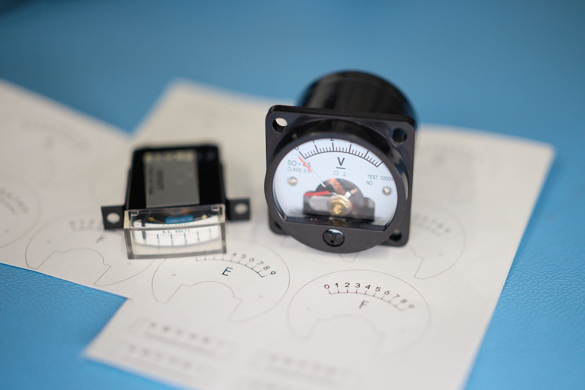
I constructed the display itself out of six generic “SO-45” panel voltmeters from Amazon, plus one vintage edgewise voltmeter scored on eBay. The meters are fitted with custom faces printed on adhesive paper (template file):
Display panel, meters with original faces.
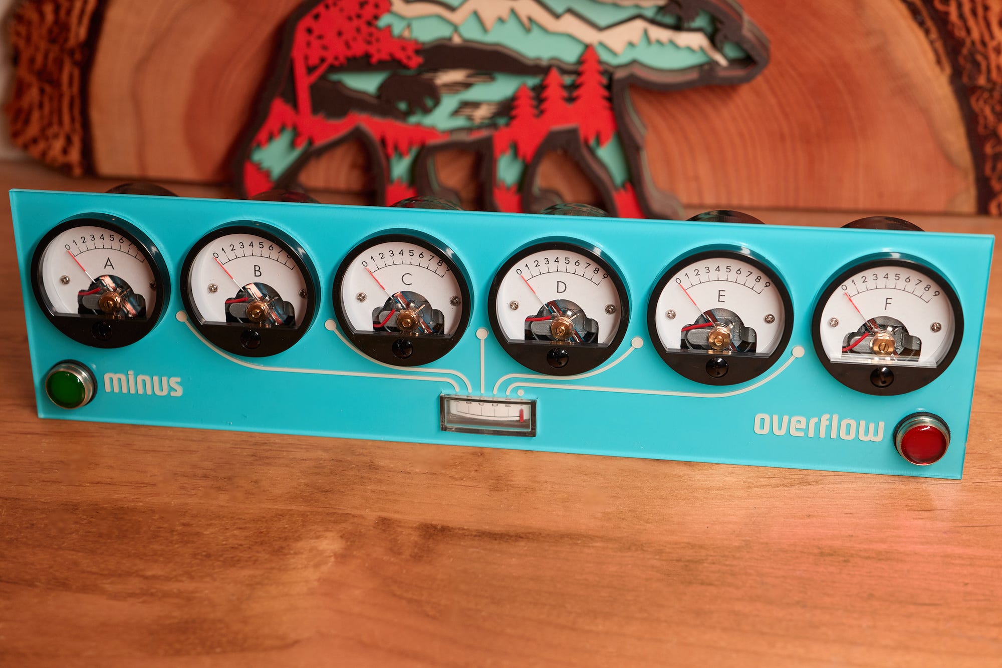
Here’s the assembled panel, also embellished with two Dialight 656 series panel indicators (catalog page) that signal negative results and overflows:
Panel close-up.
And yep, the edgewise meter in the middle is obviously used for floating point.
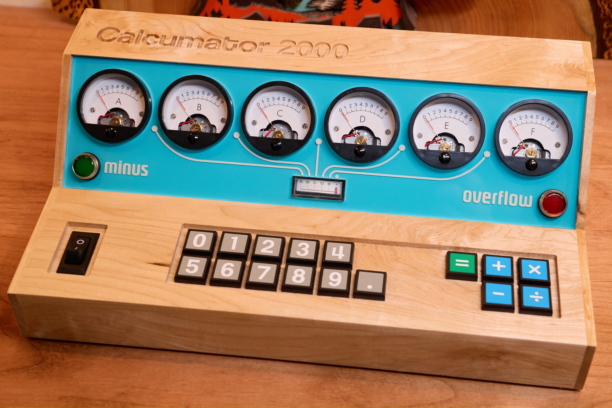
The panel was the easy part; next, I had to come up with an enclosure. Because the panel is fairly massive, I decided to use a non-standard keyboard layout: ten digits and a decimal point in a two rows on the left, and then five operator keys in a cluster to the right.
A rough 3D sketch of the enclosure.
Electrically, the keypad is still a 4×4 grid with four driven rows and four column sense lines.
I made the enclosure from thin maple lumber stock resawn in my workshop. The lettering and the recessed key matrix were once again machined on a CNC mill:
Behold, typography!
Here’s a photo of the glue-up:
No such thing as too many clamps.
The keypad uses sixteen relatively fancy 18×18 mm NKK JF series tactile switches (catalog here). I made custom vinyl decals for each key.
Here’s the photo of the finished enclosure:
Calcumator 2000 in all its glory.
The final portion of the project is the control circuitry. Some folks egged me on to implement analog calculations, but that would make the calculator even less practical — and if you want to take that route, purely-mechanical designs are more fun. So, the brains of the operation is an 8-bit AVR128DA28 MCU.
The chip is powered directly from a 5 V wall wart. It uses pulse-width modulation on seven digital lines (PD0-PD6) to drive the meters, a 4×4 sense-drive grid (PA0-PA3 / PA4-PA7) to scan the keypad, and two lines (PC0, PC1) for the indicator lamps.
I’ll spare you the walkthrough of the software architecture because it’s fairly straightforward. About the most interesting part is the implementation of fixed-point (6+5 digit) arithmetic to avoid the accuracy issues related to floats. You can download the source here; it’s short and commented well.
As discussed earlier on this blog, calculator UI is hell and the code makes several choices related to that. It allows repeated operations by pressing “+”, “×”, or “÷” twice, but reserves “-” as a prefix for changing sign, except if pressed right after the equals key. It also interprets dual “=” as an instruction to clear calculator state because the keypad doesn’t have a dedicated “C” button.
And now, the moment you’ve all been waiting for. It shows the handling of fractions, negative numbers, and error conditions:
That’s all.
📖
If you liked the article, you’ll enjoy The Secret Life of Circuits. It’s a richly illustrated, lucid introduction to electronics — from the physics of conduction to embedded system programming. It features 290+ color diagrams, 420+ pages of original content, and zero AI.